

Introduction: The "Diving Board" Effect
In many automation setups, the load isn't centered directly over the Linear Module carriage. Instead, it hangs off the side—this is a Cantilevered Load.
While TOCO modules are built for high rigidity, an excessive overhang creates a "lever arm" effect that can multiply the stress on the internal bearings by 5x or even 10x.
1. The Physics of the Moment Load
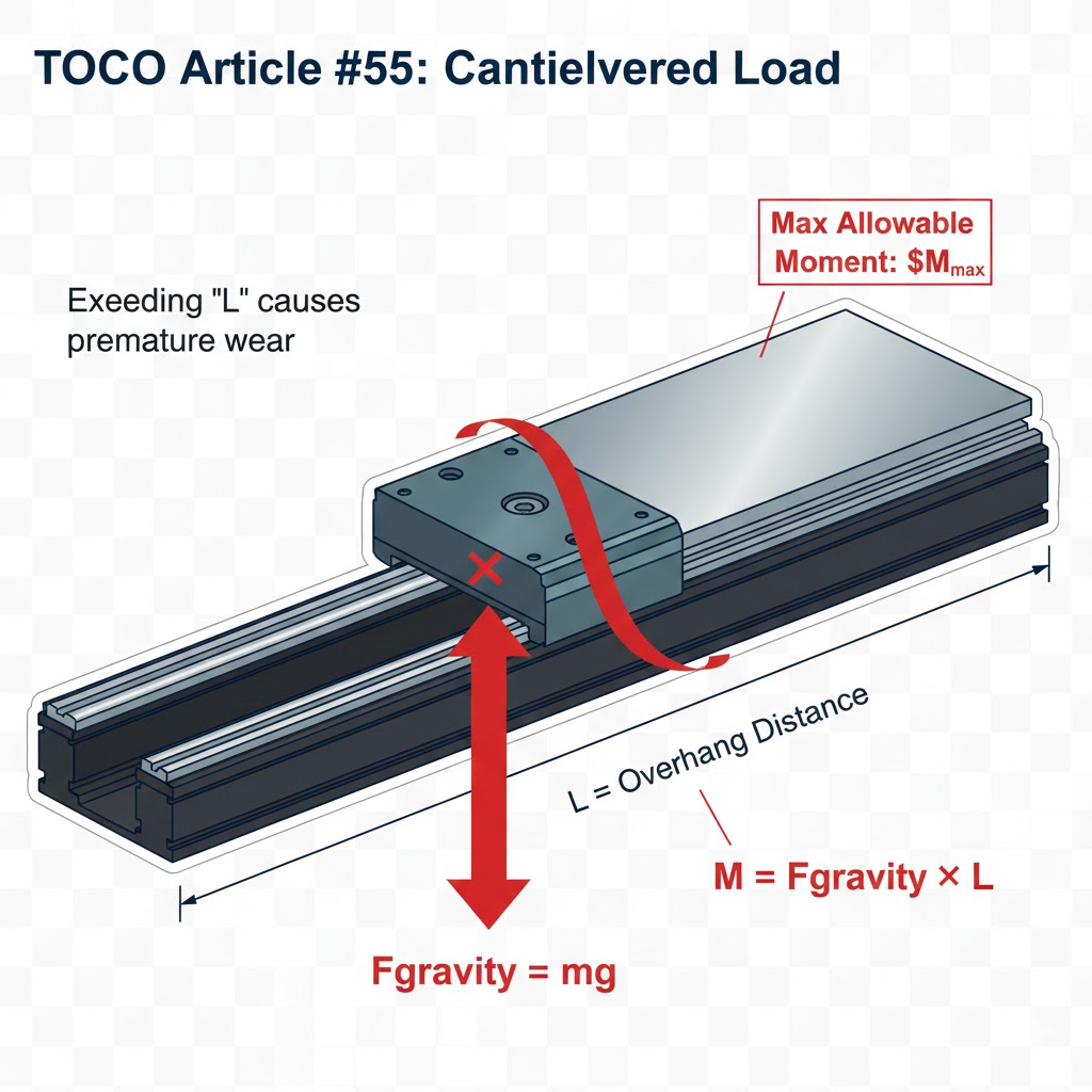
A cantilevered load creates what engineers call a Moment (M).
Formula: M = Fx d (Force multiplied by the distance from the center of the rail).
Even a light 5kg payload can damage a rail if it is hanging 500mm away from the carriage, because the "Moment" force at the bearing is massive.
2. Pitch, Roll, and Yaw: Which one is your enemy?
Roll (Mx): The load hangs off the side. This is the most common cause of "binding" in linear guides.
Pitch (My): The load is far in front of or behind the carriage. This causes the front bearings to "dig" into the rail.
Yaw (Mz): A horizontal twisting force, common in robotic arm movements.
3. How to Calculate Allowable Overhang
Every TOCO Mono Stage has a rated Static Permissible Moment (Mo).
Identify the weight of your payload.
Measure the distance from the center of the carriage to the center of the payload.
Ensure your calculated moment is at least 2x lower than the rated limit in the TOCO catalog to account for "dynamic" forces (stops and starts).
4. Solutions for Massive Overhangs
If your design requires a long reach:
Dual Rail Setup: Use two linear rails in parallel to distribute the roll moment.
Support Brackets: Use an auxiliary support guide if the overhang exceeds the module's width by more than 3:1.
 English
 German
 French
 Russian
 Spanish
 Japanese
 Korean
 Khmer
 Portuguese
 Ukrainian
 Arabic
 Italian
 Afrikaans
 Albanian
 Armenian
 Azerbaijani
 Basque
 Belarusian
 Bulgarian
 Catalan
 Croatian
 Czech
 Danish
 Dutch
 Estonian
 Filipino
 Finnish
 Galician
 Georgian
 Greek
 Haitian Creole
 Hebrew
 Hindi
 Hungarian
 Icelandic
 Indonesian
 Irish
 Latvian
 Lithuanian
 Macedonian
 Malay
 Maltese
 Norwegian
 Persian
 Polish
 Romanian
 Serbian
 Slovak
 Slovenian
 Swahili
 Swedish
 Thai
 Turkish
 Urdu
 Vietnamese
 Welsh
 Yiddish