

When we talk about the accuracy of a TOCO linear guide, we usually focus on "Running Parallelism"—how straight the carriage moves along the rail.
However, in three-dimensional space, a carriage doesn't just move; it can slightly rotate. These rotations, known as Pitch, Yaw, and Roll, are the primary culprits behind "Volumetric Error" in multi-axis machines.
The 6 Degrees of Freedom
Every linear axis has six potential errors:
Linear Positioning: Accuracy in the direction of travel.
Horizontal Straightness: Deviation to the left or right.
Vertical Straightness: Deviation up or down.
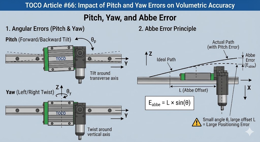
Pitch: Rotation around the transverse axis (tilting forward/backward).
Yaw: Rotation around the vertical axis (turning left/right).
Roll: Rotation around the longitudinal axis (twisting).
The "Abbe Error": Why Small Angles Cause Big Problems
The most dangerous part of Pitch and Yaw is the Abbe Error. This occurs when the point of measurement (or the tool tip) is offset from the center of the rail.
Imagine your CNC spindle is 200 mm away from the linear rail. If the TOCO carriage has a Pitch error of only 0.01°, that tiny angle is magnified over the 200 mm distance.
E_Abbe = L x sin(θ)
At a 200 mm offset (L), a 0.01° tilt (θ) creates a positioning error of roughly 35 microns at the tool tip—even if the linear scale says the carriage is in the "perfect" spot.
Volumetric Accuracy in Multi-Axis Systems
In a 3-axis machine (X, Y, Z), these errors stack. A Yaw error on the X-axis might push the Y-axis out of alignment, which then compounds with a Pitch error on the Z-axis.
Result: The machine might be accurate at the center of the table, but as the tool moves toward the corners, the "Volumetric Accuracy" degrades.
The TOCO Solution: This is why selecting a High Precision (H) or Precision (P) grade rail is vital. It’s not just about the rail being straight; it’s about the bearing races being ground with such tight tolerances that angular "wobble" is minimized.
How to Mitigate Pitch and Yaw Errors
Minimize Offsets: Keep your tool tip or sensor as close to the center of the guide rail as possible.
Mounting Surface Precision: A linear guide is only as straight as the surface it is bolted to. High-precision machines require "scraped" or precision-ground mounting shoulders.
Wider Rail Spacing: Increasing the distance between two parallel rails significantly reduces Yaw and Pitch tendencies.
Conclusion
If you are building a high-precision inspection machine or a 5-axis mill, you cannot ignore the geometry of the axis.
By understanding how Pitch and Yaw affect your tool tip via the Abbe Principle, you can design a more rigid system and get the most out of your TOCO precision components.

 English
 German
 French
 Russian
 Spanish
 Japanese
 Korean
 Khmer
 Portuguese
 Ukrainian
 Arabic
 Italian
 Afrikaans
 Albanian
 Armenian
 Azerbaijani
 Basque
 Belarusian
 Bulgarian
 Catalan
 Croatian
 Czech
 Danish
 Dutch
 Estonian
 Filipino
 Finnish
 Galician
 Georgian
 Greek
 Haitian Creole
 Hebrew
 Hindi
 Hungarian
 Icelandic
 Indonesian
 Irish
 Latvian
 Lithuanian
 Macedonian
 Malay
 Maltese
 Norwegian
 Persian
 Polish
 Romanian
 Serbian
 Slovak
 Slovenian
 Swahili
 Swedish
 Thai
 Turkish
 Urdu
 Vietnamese
 Welsh
 Yiddish